VOLVO D13 ENGINE Manual service
VOLVO D13 ENGINE SERVICE MANUAL – PDF DOWNLOAD
DESCRIPTION:
Volvo D13 Engine Service Manual – PDF DOWNLOAD
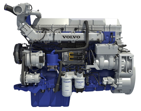
Volvo D13 Engine
SYSTEM OVERVIEW:
The Engine Management System (EMS) controls many engine functions such as: fuel timing and delivery, engine protection functions, engine brake operation, EGR valve function and the turbocharger nozzle function. The Engine Electronic Control Unit (EECU) along with other supporting control units and sensors are responsible for monitoring and controlling these functions.
These control units communicate through the J1939 high speed serial data line to share data. In addition to their control functions, the modules have on-board diagnostic capabilities. The onboard diagnostics are designed to detect faults or abnormal conditions that are not within their operating parameters. When the system detects a fault or abnormal condition, the fault will be logged in one or both of the modules’ memory. The vehicle operator will be advised that a fault has occurred by the illumination of a malfunction indicator lamp and a message in the driver information display, if equipped.
The module may initiate the engine shutdown procedure if the system determines that the abnormal condition could damage the engine. In some situations, the system will enter the “limp home” mode. Limp home mode allows continued vehicle operation but, the system may substitute a sensor or signal value that may result in reduced engine performance.
Fault codes logged in the system memory, can later be read to aid in diagnosing the fault. These faults can be read via a diagnostic computer or through the instrument cluster display, if equipped. The “Premium Tech Tool” (PTT) is the preferred tool for performing diagnostic work. Using a diagnostic computer (or PTT) connected to the Serial Communication Port, expands the technicians diagnostic capabilities with additional data and tests. For diagnostic software, contact your local dealer.
TABLE OF CONTENTS:
Volvo D13 Engine Service Manual – PDF DOWNLOAD
1 VOLVO D13 ENGINE3
11 SYSTEM OVERVIEW3
12 ENGINE OVERVIEW6
13 ENGINE OIL 7
131 General7
132 Oil Quality 7
133 Oil Change Intervals8
134 Oil Filters 9
135 Synthetic Lubrication 9
136 Oil Viscosity 9
137 Oil Additives9
138 Oil Consumption9
139 Oil Change10
1310 Oil Filters Change10
1311 Checking The Oil Level 11
14 POWER PLANT ASSEMBLY REMOVAL11
15 POWER PLANT ASSY INSTALLATION14
16 ENGINE MOUNTS 14
2 DETROIT DIESEL SERIES 60 ENGINE16
21 DDEC VI SYSTEM16
22 HARNESSES16
23 ENGINE OVERVIEW17
24 DDEC VI SENSORS18
25 PREVOST INSTALLED SENSORS 19
26 MOTOR CONTROL MODULE (MCM)19
27 COMMON POWERTRAIN CONTROLLER (CPC)19
28 DDEC VI DIAGNOSTICS19
281 Diagnostic system 19
282 Check Engine Telltale Light (AWL) 20
283 Stop Engine Warning Light (RSL) 20
284 Stop Engine Override Switch (SEO) 20
285 Diagnostic Data Link (DDL) Connectors 20
29 READING DIAGNOSTIC CODES – FLASHING LIGHT METHOD: 20
210 DDEC VI CPC DIAGNOSTIC CODES LIST 21
211 DDEC VI MCM DIAGNOSTIC CODES LIST 28
212 ENGINE OIL LEVEL 39
213 ENGINE OIL AND FILTER CHANGE 40
214 RECOMMENDED ENGINE OIL TYPE41
215 POWER PLANT ASSEMBLY REMOVAL41
216 POWER PLANT ASSY INSTALLATION45
217 JAKE BRAKE45
218 ENGINE MOUNTS 45
3 ELECTRONIC FOOT PEDAL ASSEMBLY (EFPA) & THROTTLE POSITION SENSOR 46
4 ENGINE TROUBLESHOOTING GUIDE47
5 SPECIFICATIONS49
51 SERIES 60 ENGINE49
52 VOLVO D13 ENGINE 50
Section 01: ENGINE
PA1561 2
ILLUSTRATIONS
FIGURE 1: D13F ENGINE, ALTERNATOR SIDE (TYPICAL) 6
FIGURE 2: D13F ENGINE, TURBO SIDE (TYPICAL) 7
FIGURE 3: D13F OIL FILTERS9
FIGURE 4: OIL FILTER WRENCH10
FIGURE 5: OIL FITER REPLACEMENT11
FIGURE 6: ENGINE OIL FILLING TUBE 11
FIGURE 7: ENGINE OIL LEVEL DIPSTICK 11
FIGURE 8: BELT TENSIONER VALVE12
FIGURE 9: ENGINE COMPARTMENT H3 COACHES (TYPICAL) 14
FIGURE 10: VOLVO ENGINE POWER PLANT CRADLE INSTALLATION 15
FIGURE 11: VEHICLE INTERFACE HARNESS (GENERAL APPLICATION SHOWN)16
FIGURE 12: DETROIT DIESEL 2007 SERIES 60 ENGINE (TYPICAL 18
FIGURE 13: MOTOR CONTROL MODULE (MCM)19
FIGURE 14: CPC19
FIGURE 15: THE CPC COMMUNICATES OVER THE J1587 AND J1939 DATA LINKS TO THE VEHICLE 19
FIGURE 16: FLASHING FAULTS CODES 21
FIGURE 17: ENGINE OIL LEVEL DIPSTICK 39
FIGURE 18: OIL RESERVE TANK 39
FIGURE 19: UNDER VEHICLE VIEW 40
FIGURE 20: ENGINE COMPARTMENT 42
FIGURE 21: ENGINE COMPARTMENT H3 COACHES (TYPICAL) 44
FIGURE 22: ENGINE COMPARTMENT VIP (TYPICAL)44
FIGURE 23: POWER PLANT CRADLE INSTALLATION45
FIGURE 24: ELECTRONIC FOOT PEDAL ASSEMBLY46














Reviews
There are no reviews yet.