Volvo All Engines (2004 Emissions) Fault Code: SID 2 FMI 12 Fuel Injector Unit #2
Fault Condition: If the Engine Management System (EMS) Module detects a fault in the electrical circuit while attempting to operate the Fuel Injector Unit, the Electronic Malfunction Lamp (EML) will turn ON and code SID 2 will set.
Possible repairs:
Turn the ignition switch OFF first.
1) Disconnect the harness electrical connector from Fuel Injector Unit #2. Check for continuity between the pins 1 and 2 of the Fuel Injector Unit #1. If the resistance is NOT between 0.9-5.2 Ohms at 68°F (20°C) or 1.5-5.8 Ohms at 218°F (103°C), Fuel Injector #2 is faulty and must be replaced.
2) Disconnect the harness electrical connectors from Fuel Injector Unit #2. Check for continuity from pins 1 and 2 on Fuel Injector Unit #2 to a good ground. If continuity exists, the Fuel Injector Unit #2 is shorted to ground and must be replaced.
3) Disconnect connectors A and B from the Engine Management System (EMS) Module. Disconnect the harness connector from Fuel Injector Unit #2. Check for continuity between the Fuel Injector Unit #2 harness connector pin 1 and 2 and a good ground.
4) Disconnect connectors A and B from the (EMS) Module. Check for continuity between EMS Module harness connector A pin 62 and pin 1 of the Fuel Injector Unit #2. If there is NO continuity, repair the open in the circuit.
5) Disconnect connectors A and B from the (EMS) Module. Check for continuity between pin 2 of the the Fuel Injector Unit #2 and EMS Module harness connector A pin 20. If there is NO continuity, repair the open in the circuit.
6) Disconnect connectors A and B from the (EMS) Module. Turn the ignition key ON. Measure the voltage between EMS Module connector A pin 62 and a good ground. If voltage is present, the voltage supply circuit is shorted to voltage. Locate and repair the short circuit.
7) Disconnect (EMS) Module connectors A and B. Disconnect the harness connector from Fuel Injector Unit #2. Turn the ignition key ON. Measure the voltage between the EMS Module connector A pin 20 and a good ground. If voltage is present, the Fuel Injector Unit #2 control line is shorted to voltage. Locate and repair the short.
8) Disconnect connector A and B from the (EMS) Module. Disconnect the harness electrical connector from the Fuel Injector Unit #2. Check for continuity between EMS Module harness connector A pin 20 and/or 62 and all other pins on EMS Module connectors A and B. If continuity exists, the Fuel Injector Unit #2 circuit is shorted to one of the other EMS Module circuits. Locate and repair the short circuit.
9) Disconnect the harness electrical connector from Fuel Injector Unit #2. Check for continuity between the pins 3 and 4 of the Fuel Injector Unit #2. If the resistance is NOT between 0.9-5.2 Ohms at 68°F (20°C) or 1.5-5.8 Ohms at 218°F (103°C), Fuel Injector #2 is faulty and must be replaced.
10) Disconnect the harness electrical connectors from Fuel Injector Unit #2. Check for continuity from either pin on Fuel Injector Unit #2 to a good ground. If continuity exists, the Fuel Injector Unit #2 is shorted to ground and must be replaced.
11) Disconnect connectors A and B from the (EMS) Module. Disconnect the harness connector from Fuel Injector Unit #2. Check for continuity between the Fuel Injector Unit #2 harness connector pin 3 and pin 4 and a good ground. If continuity exists, the circuit is shorted to ground. Locate and repair the short circuit.
12) Disconnect connectors A and B from the (EMS) Module. Disconnect the harness connector from Fuel Injector Unit #2. Check for continuity between EMS Module harness connector A pin 59 and pin 3 of the Fuel Injector Unit #2. If there is NO continuity, repair the open in the circuit.
13) Disconnect connectors A and B from the (EMS) Module. Disconnect the harness connector from Fuel Injector Unit #2. Check for continuity between pin 4 of the the Fuel Injector Unit #2 and EMS Module harness connector A pin 24. If there is NO continuity, repair the open in the circuit.
14) Disconnect connectors A and B from the (EMS) Module. Turn the ignition key ON. Measure the voltage between EMS Module connector A pin 59 and a good ground. If voltage is present, the voltage supply circuit is shorted to voltage. Locate and repair the short circuit.
15) Disconnect (EMS) Module connectors A and B. Disconnect the harness connector from Fuel Injector Unit #2. Turn the ignition key ON. Measure the voltage between the EMS Module connector A pin 24 and a good ground. If voltage is present, the Fuel Injector Unit #2 control line is shorted to voltage. Locate and repair the short.
16) Disconnect connector A and B from the (EMS) Module. Disconnect the harness electrical connector from the Fuel Injector Unit #2. Check for continuity between EMS Module harness connector A pin24 and/or 59 and all other pins on EMS Module connectors A and B. If continuity exists, the Fuel Injector Unit #2 circuit is shorted to one of the other EMS Module circuits. Locate and repair the short circuit.
17) Disconnect connectors A and B from the EMS Module. Visually inspect EMS Module connectors A and B for dirt, loose pins or deformed contacts. If a pin feels loose or appears damaged, repair the connector.
18) Ensure that there is fuel in the fuel tank. Inspect the fuel lines between the tank and the transfer pump for sharp bends or kinks, and repair as needed. Check for air in the fuel system, and repair as needed. Check the fuel pressure at the secondary fuel filter outlet. If the fuel pressure is NOT within specifications, perform any required fuel system repairs. Remove Fuel Injector Unit #2 from the engine and inspect for surface rust between the O-rings. If rust is present, locate the source of the fuel contamination and replace any damaged components. If all of the mechanical fuel system components are in good working order, replace the EMS Module and retest the system.
Related
-
CAT CDVR PC Software – Caterpillar Digital Voltage Regulator (CDVR) WINDOWS 10
CAT $45.00Rated 0 out of 5 -
download Hitachi Construction Machinery MPDr Ver 3.7.0.0 [10.2020] Diagnostic Software
Hitachi $76.00Rated 0 out of 5 -
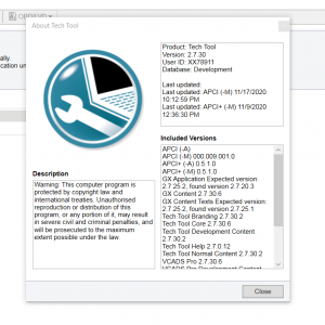
VOLVO PREMIUM TECH TOOL PTT 2.7.30 Developer + Devtool + INSTALATION VIDEO!
Trucks software $60.00Rated 0 out of 5
Related products
-
Allison 1000 & 2000 Gen 4 Fault Codes: P0871 Transmission Pressure Switch Solenoid E Circuit Stuck Open
1000 & 2000 Gen 4 $50.00Rated 0 out of 5 -
Allison 1000 & 2000 Gen 4 Fault Codes: U1064 J1850 (Class 2) TBC Controller State of Health Failure
1000 & 2000 Gen 4 $50.00Rated 0 out of 5 -
Allison 1000 & 2000 Gen 4 Fault Codes: P0875 Transmission Reverse Pressure Switch Circuit Malfunction
1000 & 2000 Gen 4 $50.00Rated 0 out of 5 -
Allison 1000 & 2000 Gen 4 Fault Codes: U0100 CAN Bus ECM Error
1000 & 2000 Gen 4 $50.00Rated 0 out of 5 -
Allison 1000 & 2000 Gen 4 Fault Codes: P0847 Transmission Pressure Switch Solenoid D Circuit Stuck Closed
1000 & 2000 Gen 4 $50.00Rated 0 out of 5 -
Allison 1000 & 2000 Gen 4 Fault Codes: U0073 CAN Bus Reset Counter Overrun
1000 & 2000 Gen 4 $50.00Rated 0 out of 5 -
Allison 1000 & 2000 Gen 4 Fault Codes: P1779 Engine Torque Delivered To TCM Signal
1000 & 2000 Gen 4 $50.00Rated 0 out of 5 -
Allison 1000 & 2000 Gen 4 Fault Codes: P0846 Transmission Pressure Switch Solenoid D Circuit Stuck Open
1000 & 2000 Gen 4 $50.00Rated 0 out of 5 -
Allison 1000 & 2000 Gen 4 Fault Codes: P1891 Engine Throttle Position Sensor Pulse Width Modulation (PWM) Signal Low Input
1000 & 2000 Gen 4 $50.00Rated 0 out of 5 -
Allison 1000 & 2000 Gen 4 P0719 Brake Switch ABS Input Low
1000 & 2000 Gen 4 $50.00Rated 0 out of 5 -
Allison 1000 & 2000 Gen 4 Fault Codes: U2105 CAN Bus ECM Error
1000 & 2000 Gen 4 $50.00Rated 0 out of 5 -
Allison 1000 & 2000 Gen 4 Fault Codes: P0123 Pedal Position Sensor Circuit High Voltage
1000 & 2000 Gen 4 $50.00Rated 0 out of 5 -
Allison 1000 & 2000 Gen 4 Fault Codes: U1041 J1850 (Class 2) ABS Controller State of Health Failure
1000 & 2000 Gen 4 $50.00Rated 0 out of 5 -
Allison 1000 & 2000 Gen 4 Fault Codes: U0032 J1850 (Class 2) Serial Data Communication Link High
1000 & 2000 Gen 4 $50.00Rated 0 out of 5


![download Hitachi Construction Machinery MPDr Ver 3.7.0.0 [10.2020] Diagnostic Software](https://i0.wp.com/www.ecuforcetruck.com/wp-content/uploads/2023/05/MPDR-3.7.00.png?resize=300%2C300&ssl=1)
![download Hitachi Construction Machinery MPDr Ver 3.7.0.0 [10.2020] Diagnostic Software](https://www.ecuforcetruck.com/wp-content/uploads/2023/05/MPDR.png)


