
Related products
-
Allison 1000 & 2000 Gen 4 Fault Codes: U1064 J1850 (Class 2) TBC Controller State of Health Failure
1000 & 2000 Gen 4 $50.00 -
Allison 1000 & 2000 Gen 4 Fault Codes: P2773 Torque Control Request Ignored – ECM/TCM
1000 & 2000 Gen 4 $50.00 -
Allison 1000 & 2000 Gen 4 Fault Codes: U1300 J1850 (Class 2) Serial Data Communication Link Low
1000 & 2000 Gen 4 $50.00 -
Allison 1000 & 2000 Gen 4 Fault Codes: U0031 J1850 (Class 2) Serial Data Communication Link Low
1000 & 2000 Gen 4 $50.00 -
Allison 1000 & 2000 Gen 4 Fault Codes: U1301 J1850 (Class 2) Serial Data Communication Link Low
1000 & 2000 Gen 4 $50.00 -
-
Allison 1000 & 2000 Gen 4 Fault Codes: P0870 Transmission Pressure Switch Solenoid E Circuit
1000 & 2000 Gen 4 $50.00 -
Allison 1000 & 2000 Gen 4 Fault Codes: U0032 J1850 (Class 2) Serial Data Communication Link High
1000 & 2000 Gen 4 $50.00 -
Allison 1000 & 2000 Gen 4 Fault Codes: U1000 Class 2 Loss of Serial Data Communication
1000 & 2000 Gen 4 $50.00 -
Allison 1000 & 2000 Gen 4 Fault Codes: P0122 Pedal Position Sensor Circuit Low Voltage
1000 & 2000 Gen 4 $50.00 -
-
-
-
-

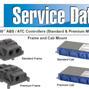
Bendix ABS EC-30 Fault Code: SID 251 FMI 3
Bendix ABS