Volvo All Engines (2004 Emissions) Fault Code: PID 153 FMI 5 Crankcase Pressure Sensor
Fault Condition: The Electronic Malfunction Lamp (EML) will illuminate when the Crankcase Pressure (CP) Sensor signal line voltage is less than 0.3 volts or greater than 4.75 volts. If the signal line voltage is between 0.3 volts and 4.75 volts the fault will become inactive.
Possible repairs:
Turn the ignition key OFF first.
1) Check for continuity between Crankcase Pressure (CP) Sensor harness connector pin 2 (signal line) and a good ground. If continuity exists, locate and repair the short circuit to ground.
2) Disconnect EMS Module connector B. Check for continuity between Crankcase Pressure (CP) Sensor harness connector pin 1 (reference voltage line) and EMS Module harness connector B pin 17. If there is NO continuity, repair the open in the harness reference voltage line.
3) Disconnect the Crankcase Pressure (CP) Sensor. Disconnect EMS Module connectors A and B. Check for continuity between EMS Module harness connector B pin 28 (signal line) and all other pins in EMS Module harness
connectors A and B. Visually check EMS Module connector B pin 28 for a short circuit. If continuity exists or if there is a visual short, repair the short circuit to the signal line. If there is NO continuity or visual short, replace the EMS Module.
4) Disconnect the Crankcase Pressure (CP) Sensor. Disconnect Engine Management System (EMS) Module connector B. Check for continuity between Crankcase Pressure (CP) Sensor harness connector pin 2 (signal line) and EMS Module harness connector B pin 28. If there is NO continuity, repair the open in the harness signal line.
5) Disconnect the Crankcase Pressure (CP) Sensor. Disconnect Engine Management System (EMS) Module connectors A and B. Check for continuity between EMS Module harness connector B pin 17 (reference voltage line) and all other pins in EMS Module harness connectors A and B. Visually check EMS Module connector B pin 17 for a short circuit. If continuity exists or if there is a visual short, repair the short circuit to the reference voltage line.
If there is NO continuity or visual short, replace the EMS Module.
6) Disconnect Engine Management System (EMS) Module connectors A and B. Disconnect the Crankcase Pressure (CP) Sensor. Check for continuity between EMS Module harness connector B pin 17 (reference voltage line) and all other pins in EMS Module harness connectors A and B. Visually check EMS Module connector B pin 17 for a short circuit. If continuity exists or if there is a visual short, repair the short circuit to the reference voltage line.
If there is NO continuity or visual short circuit, replace the EMS Module.
7) Visually inspect both sides of the Crankcase Pressure (CP) Sensor connector for a repairable open. If there is a repairable fault or any of the pins feel loose, repair or replace the connector.
8) Disconnect Engine Management System (EMS) Module connectors A and B. Disconnect the Crankcase Pressure (CP) Sensor. Check for continuity between EMS Module harness connector B pin 18 (ground line)
and all other pins in EMS Module harness connectors A and B. Visually check EMS Module connector B pin 18 for a short circuit. If continuity exists or if there is a visual short circuit, repair the short to the return line. If there is NO continuity or visual short circuit, replace the EMS Module.
9) Visually inspect both sides of the Crankcase Pressure (CP) Sensor connector for a repairable open. If there is a repairable fault or any of the pins feel loose, repair or replace the connector.
10) Disconnect the Crankcase Pressure (CP) Sensor. Disconnect Engine Management System (EMS) Module connector B. Check for continuity between Crankcase Pressure (CP) Sensor harness connector pin 4 (ground line) and EMS Module harness connector B pin 18. If there is NO continuity, repair the open in the harness ground line.
11) Remove the Crankcase Pressure (CP) Sensor. Connect the Crankcase Pressure (CP) Sensor to a regulated air supply with an accurate atmospheric pressure gauge. Connect a jumper wire between Crankcase Pressure (CP) Sensor pin 1 and pin 1 on the sensor harness connector. Connect a jumper wire between Crankcase Pressure (CP) Sensor pin 4 and a good ground. Turn the ignition key ON.
If the Crankcase Pressure (CP) Sensor output is correct throughout the entire pressure range, reinstall the sensor and replace the EMS Module.
If the Crankcase Pressure (CP) Sensor output is NOT correct throughout the entire pressure range, replace the Crankcase Pressure (CP) Sensor and recheck the system.
12) Visually inspect both sides of EMS Module connector B pin 18 for a repairable open in the ground line. If a repairable open is found, repair or replace EMS Module harness connector B. If the pins are making good contact, replace the EMS Module.
-
JPRO 2022 v1 Commercial Vehicle Diagnostics V1 Software Download & Installation Service ( 1 PC )
JPRO $94.00Rated 0 out of 5 -
JOHN DEERE SERVICE ADVISOR 5.3.225 DATABASE AG + CF ENGLISH 2023
John Deere $250.00Rated 0 out of 5
-
Hino Diagnostic eXplorer 2 – Hino DX2 v1.1.21.4 with keygen unlocked ( Hino trucks )
Hino $60.00Rated 0 out of 5 -
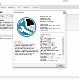
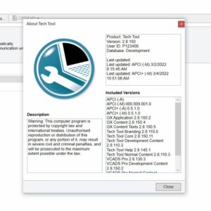
Volvo Premium Tech Tool PTT 2.8.130 Diagnostic Software 04.2022 ACPI ( 1 PC )
Trucks software $143.00Rated 0 out of 5 -
premium volvo tech tool update 2.8.150 diagnostic software 1pc
Trucks software $150.00Rated 0 out of 5 -
DAF Davie Runtime v5.6.1 Davie XDc ll [02.2019] + Expire Fix 302.00 Unlock ( Windows 7 )
DAF $70.00Rated 0 out of 5
Related products
-
Allison 1000 & 2000 Gen 4 Fault Codes: U0031 J1850 (Class 2) Serial Data Communication Link Low
1000 & 2000 Gen 4 $50.00Rated 0 out of 5 -
Allison 1000 & 2000 Gen 4 Fault Codes: P2773 Torque Control Request Ignored – ECM/TCM
1000 & 2000 Gen 4 $50.00Rated 0 out of 5 -
Allison 1000 & 2000 Gen 4 Fault Codes: P0122 Pedal Position Sensor Circuit Low Voltage
1000 & 2000 Gen 4 $50.00Rated 0 out of 5 -
Allison 1000 & 2000 Gen 4 Fault Codes: P0875 Transmission Reverse Pressure Switch Circuit Malfunction
1000 & 2000 Gen 4 $50.00Rated 0 out of 5 -
Allison 1000 & 2000 Gen 4 Fault Codes: P1891 Engine Throttle Position Sensor Pulse Width Modulation (PWM) Signal Low Input
1000 & 2000 Gen 4 $50.00Rated 0 out of 5 -
Allison 1000 & 2000 Gen 4 Fault Codes: U0100 CAN Bus ECM Error
1000 & 2000 Gen 4 $50.00Rated 0 out of 5 -
Allison 1000 & 2000 Gen 4 Fault Codes: P0871 Transmission Pressure Switch Solenoid E Circuit Stuck Open
1000 & 2000 Gen 4 $50.00Rated 0 out of 5 -
Allison 1000 & 2000 Gen 4 Fault Codes: P0876 Transmission Reverse Pressure Switch Circuit Stuck Open
1000 & 2000 Gen 4 $50.00Rated 0 out of 5 -
Allison 1000 & 2000 Gen 4 Fault Codes: U1064 J1850 (Class 2) TBC Controller State of Health Failure
1000 & 2000 Gen 4 $50.00Rated 0 out of 5 -
Allison 1000 & 2000 Gen 4 Fault Codes: U1000 Class 2 Loss of Serial Data Communication
1000 & 2000 Gen 4 $50.00Rated 0 out of 5 -
Allison 1000 & 2000 Gen 4 Fault Codes: P1892 Throttle Position Sensor Pulse Width Modulation (PWM) Signal High Input
1000 & 2000 Gen 4 $50.00Rated 0 out of 5 -
Allison 1000 & 2000 Gen 4 Fault Codes: U1016 Class 2 J1850 (Class 2) Powertrain Controller State of Health Failure
1000 & 2000 Gen 4 $50.00Rated 0 out of 5 -
Allison 1000 & 2000 Gen 4 Fault Codes: P0218 Transmission Fluid Over Temperature Condition
1000 & 2000 Gen 4 $50.00Rated 0 out of 5 -
Allison 1000 & 2000 Gen 4 Fault Codes: U1041 J1850 (Class 2) ABS Controller State of Health Failure
1000 & 2000 Gen 4 $50.00Rated 0 out of 5 -
Allison 1000 & 2000 Gen 4 P0719 Brake Switch ABS Input Low
1000 & 2000 Gen 4 $50.00Rated 0 out of 5
-
SERVICE MANUAL International Engines DT466E & DT530E (1999 & Older)
INTERNATIONAL ENGINES $31.00Rated 0 out of 5