Volvo All Engines (2004 Emissions) Fault Code: PID 105 FMI 4 Boost Air Pressure / Temperature Sensor
Fault Condition: The Electronic Malfunction Lamp (EML) will turn on and PID 105 will set when the EMS Module senses that the Boost Pressure and Temperature Sensor signal voltage is less than 0.1 volts or greater than 4.55 volts. If the Boost Air Pressure/Temperature Sensor voltage is between 0.1 volts and 4.55 volts, the fault will become inactive.
Possible repairs:
Turn the ignition key OFF first.
1) Disconnect the Boost Air Pressure/Temperature Sensor connector. Measure the resistance between pins 1 and 2 of the Boost Air Pressure/Temperature Sensor with the ambient air temperature between 32° and 203°F (0° and 95°C). If the measured resistance is NOT between 5887 and 213.67 ohms, replace the sensor.
2) Disconnect the Boost Air Pressure/Temperature Sensor connector. Check for continuity between pin 1 of the Boost Air Pressure/Temperature Sensor and a good ground. Check for continuity between pin 2 of the Boost Air Pressure/Temperature Sensor and a good ground. Check for continuity between pin 3 of the Boost Air Pressure/Temperature Sensor and a good ground. Check for continuity between pin 4 of the Boost Air Pressure/Temperature Sensor and a good ground. If continuity exists on any pin, replace the Boost Air Pressure/Temperature Sensor.
3) Disconnect the Boost Air Pressure/Temperature Sensor harness connector. Measure the resistance between pins 1 and 2 of the Boost Air Pressure/Temperature Sensor with the ambient air temperature between 32° and 203°F (0° and 95°C). If the measured resistance is NOT between 5887 and 213.67 ohms, replace the Boost Air Pressure/Temperature Sensor.
4) disconnect the Boost Air Pressure/Temperature Sensor harness connector. Disconnect Engine Management System (EMS) Module connector A. Check for continuity between pin 2 of the Boost Air Pressure/Temperature Sensor harness connector and Engine Management System (EMS) Module harness connector A pin 47. If there is NO continuity, locate and repair the open in the signal circuit between the Boost Air Pressure/Temperature Sensor harness connector and Engine Management System (EMS) Module harness connector.
5) Disconnect the Boost Air Pressure/Temperature Sensor harness connector. Connect connector A to the Engine Management System (EMS) Module. Turn the ignition key ON. Measure the voltage between pin 2 of the
Boost Air Pressure/Temperature Sensor harness connector and a good ground. If the measured voltage is between 4.8 and 5.15 volts, check the Boost Air Pressure/Temperature Sensor harness connector for deformed pins or insufficient contact with the Boost Air Pressure/Temperature Sensor pins. If the pins are not damaged, replace the Boost Air Pressure/Temperature Sensor and retest the system. If PID 105 is still active, replace the EMS Module and retest the system.
6) Connect the Boost Air Pressure/Temperature Sensor harness connector. Connect connector A to the Engine Management System (EMS) Module. Turn the ignition key ON. If PID 105 is still active, check the Engine Management System (EMS) Module and connectors A, and B for dirt, loose or shorted pins, or any other repairable damage. If no problems are evident, or are NOT repairable, replace the Boost Air Pressure/Temperature Sensor and retest the system. If PID 105 is still active, replace the EMS Module and retest the system. If PID 105 is NOT active, the diagnostic procedures have corrected the problem. Check all connectors to ensure proper connections.
-
DPF EGR SCR BAC ERG Delete & Flash CAAT Cummings Detroit Dodge Mack Volvo Collection of DELETE files
CAT $200.00Rated 0 out of 5 -
Volvo PROSIS Offline 2019 Parts Catalog Installation Service
Trucks software $45.00Rated 0 out of 5
-
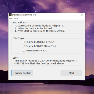
CAT Engine Reprogramming Tool for flash programming C1.8, C2.4, C3.8 & C3.3B + Guide
CAT $50.00Rated 0 out of 5 -
Hino Diagnostic eXplorer 2 – Hino DX2 1.1.19.1 with keygen unlocked ( Hino trucks )
Hino $50.00Rated 0 out of 5 -
Scania SDP3 2.48.6 Diagnosis & Programming for VCI 3 VCI3 without Dongle
Scania $30.00Rated 0 out of 5 -
Volvo Impact 2021 Trucks & Buses 06.2021 DVD 9116 Spare Parts Catalog
Trucks software $55.00Rated 0 out of 5 -
premium volvo tech tool update 2.8.150 diagnostic software 1pc
Trucks software $150.00Rated 0 out of 5 -
download Hitachi Construction Machinery MPDr Ver 3.7.0.0 [10.2020] Diagnostic Software
Hitachi $76.00Rated 0 out of 5
Related products
-
Allison 1000 & 2000 Gen 4 Fault Codes: U2105 CAN Bus ECM Error
1000 & 2000 Gen 4 $50.00Rated 0 out of 5 -
Allison 1000 & 2000 Gen 4 Fault Codes: U0031 J1850 (Class 2) Serial Data Communication Link Low
1000 & 2000 Gen 4 $50.00Rated 0 out of 5 -
Allison 1000 & 2000 Gen 4 Fault Codes: P0218 Transmission Fluid Over Temperature Condition
1000 & 2000 Gen 4 $50.00Rated 0 out of 5 -
Allison 1000 & 2000 Gen 4 Fault Codes: U0032 J1850 (Class 2) Serial Data Communication Link High
1000 & 2000 Gen 4 $50.00Rated 0 out of 5 -
Allison 1000 & 2000 Gen 4 Fault Codes: U1301 J1850 (Class 2) Serial Data Communication Link Low
1000 & 2000 Gen 4 $50.00Rated 0 out of 5 -
Allison 1000 & 2000 Gen 4 Fault Codes: U1016 Class 2 J1850 (Class 2) Powertrain Controller State of Health Failure
1000 & 2000 Gen 4 $50.00Rated 0 out of 5 -
Allison 1000 & 2000 Gen 4 Fault Codes: U1041 J1850 (Class 2) ABS Controller State of Health Failure
1000 & 2000 Gen 4 $50.00Rated 0 out of 5 -
Allison 1000 & 2000 Gen 4 Fault Codes: P0876 Transmission Reverse Pressure Switch Circuit Stuck Open
1000 & 2000 Gen 4 $50.00Rated 0 out of 5 -
Allison 1000 & 2000 Gen 4 Fault Codes: P2771 Four-Wheel Drive Switch Circuit
1000 & 2000 Gen 4 $50.00Rated 0 out of 5 -
Allison 1000 & 2000 Gen 4 Fault Codes: U0073 CAN Bus Reset Counter Overrun
1000 & 2000 Gen 4 $50.00Rated 0 out of 5 -
Allison 1000 & 2000 Gen 4 Fault Codes: U2104 CAN Bus Reset Counter Overrun
1000 & 2000 Gen 4 $50.00Rated 0 out of 5 -
Allison 1000 & 2000 Gen 4 Fault Codes: P0875 Transmission Reverse Pressure Switch Circuit Malfunction
1000 & 2000 Gen 4 $50.00Rated 0 out of 5 -
Allison 1000 & 2000 Gen 4 Fault Codes: P0848 Transmission Pressure Switch Solenoid D Circuit High
1000 & 2000 Gen 4 $50.00Rated 0 out of 5 -
Allison 1000 & 2000 Gen 4 Fault Codes: U1096 J1850 (Class 2) IPC Controller State of Health Failure
1000 & 2000 Gen 4 $50.00Rated 0 out of 5 -
Allison 1000 & 2000 Gen 4 Fault Codes: P0846 Transmission Pressure Switch Solenoid D Circuit Stuck Open
1000 & 2000 Gen 4 $50.00Rated 0 out of 5

![Volvo Penta EPC 6 Offline VMware [12.2021] VMware](https://www.ecuforcetruck.com/wp-content/uploads/2022/11/VOLVO-PENTA-2021-A-300x300.jpg)




![download Hitachi Construction Machinery MPDr Ver 3.7.0.0 [10.2020] Diagnostic Software](https://www.ecuforcetruck.com/wp-content/uploads/2023/05/MPDR-3.7.00-300x300.png)
